Animation
From the ‘Animation’ menu you will be able to do animations.
At this point you are limited to setting, showing and deleting markers,
showing the trail derived from these markers, and doing a smooth animation
moving the screen along the trail. You can also save and load an
animation.
Example
Let us start with an example.
Choose the ‘Open…’ menu item in the ‘File’
menu and choose the ‘city.ttp’ tree file from the
‘trees’ directory. Then choose the ‘Load…’
menu item in the ‘Animation’ menu and choose the
‘swirl.taf’ animation file from the ‘animations’
directory.
Finally, choose the ‘Start’ menu item in the
‘Animation’ directory.
You should now see a nice animation.
Creating your own animations
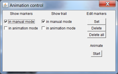
By choosing the ‘Control’ menu item in the ‘Animation’ menu you toggle the animation control dialog.

- With the ‘Set’ button you set a marker point at the current location in the 3D model. The marker is visualized as a red disc.
- By moving through the 3D model and setting multiple markers, you create a trail. The trail is visualized as a red line
- You select a marker by clicking on its red disc. With the ‘Delete’ button you can then delete it.
- To delete all markers simply click the ‘Delete all’ button.
- You can also start the animation from this dialog by clicking the ‘Start’ button.
Saving and loading animations
By choosing the ‘Save…’ and ‘Load…’
menu items in the ‘Animation’ menu you can save and load your
animations, respectively.
The first time that you choose ‘Save…’ or
‘Load…’ the ‘animations’ directory is shown,
but of course you can put your animation files anywhere you want.
Another way to create your own animations
An animation file contains all the definitions for the marker points that make up an animation.
Before we look at the structure of this file, let us first delve deeper into
what constitutes a marker point.
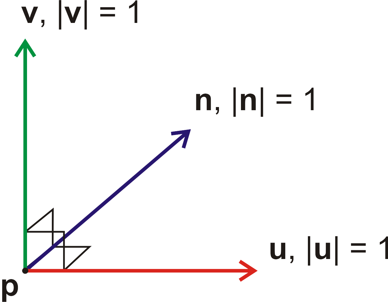
So a marker is a vector p somewhere in 3D space and it has an
orientation or orthonormal base which tells us how the screen is positioned.
The orthonormal base is defined by three vectors u, v and
n.

An animation file contains all this information. Actually, an animation file is a file that conforms to a set of simple rules:
- it is a plain text file;
- it contains zero, one or more marker definitions;
- a marker definition has the form: [MARKER] p_x p_y p_z [U] u_x u_y u_z [V] v_x v_y v_z [N] n_x n_y n_z
- the [MARKER] token indicates the start of a new marker;
- the [U], [V] and [N] tokens are for readibility;
- p_x, p_y and p_z are the x, y and z coordinates of the marker respectively;
- u_x, u_y and u_z are the x, y and z coordinates of the vector u respectively;
- v_x, v_y and v_z are the x, y and z coordinates of the vector v respectively;
- n_x, n_y and n_z are the x, y and z coordinates of the vector n respectively;
- all coordinates must be floating point numbers;
- whitespace is used as the delimiter pattern (a space, a tab, a new line, or any combination);
- the [MARKER], [U], [V] an [N] tokens are case insensitive;
- comments are preceded by an exclamation mark, the remainder of the line after the exclamation mark is considered to be a comment.
The file ‘swirl.taf’ from the example above is a valid animation file:
! animation file for The Tree Project
! see www.jogja.nl/manuals.html for details on the structure of this file

! [MARKER] p_x p_y p_z [U] u_x u_y u_z [V] v_x v_y v_z [N] n_x n_y n_z

[MARKER] 0.0 0.0 0.0 [U] 1.0 0.0 0.0 [V] 0.0 1.0 0.0 [N] 0.0 0.0 1.0
[MARKER] 350.0 500.0 1750.0 [U] 0.0 0.0 1.0 [V] 0.0 1.0 0.0 [N] -1.0 0.0 0.0
[MARKER] -150.0 1000.0 3500.0 [U] -1.0 0.0 0.0 [V] 0.0 0.0 -1.0 [N] 0.0 -1.0 0.0
[MARKER] -650.0 500.0 1750.0 [U] 0.0 0.0 -1.0 [V] 0.0 1.0 0.0 [N] 1.0 0.0 0.0
[MARKER] 0.0 0.0 0.0 [U] 1.0 0.0 0.0 [V] 0.0 1.0 0.0 [N] 0.0 0.0 1.0
Although we now know the simple rules to manually create a valid animation
file, for the file to be useful we must ensure that u, v and
n form an orthornormal base with the same orientation as the positive
parts of the x, y and z axes shown on the previous page.
Mathematically that means:
- u⊥v, or u·v = 0;
- v⊥n, or v·n = 0;
- n⊥u, or n·u = 0;
- |u| = 1;
- |v| = 1;
- |n| = 1;
- det(u v n) > 0.
If these conditions are not fulfilled then results may not be as desired. The simple example above of course satisfies these conditions. But it requires a bit more effort to manually construct an orthonormal base which is not just 'ones and zeros'.